
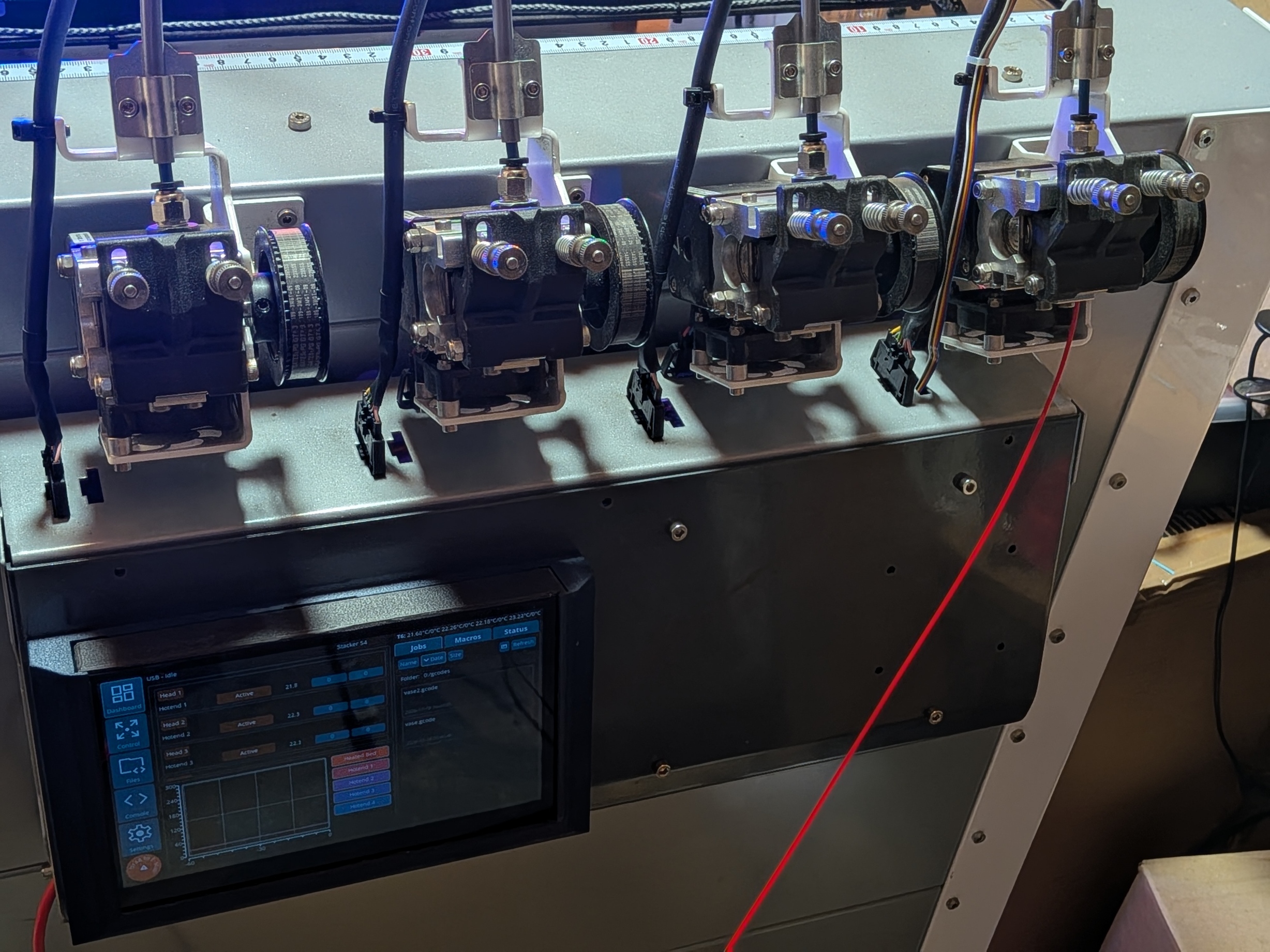

This project began as a difficult refurbishment of an ageing Stacker S4 and finished as a comprehensively re-engineered four-tool production machine. The completed printer is now designated Uni3D-S4R-4, serial Uni3D-S4R-0001. It combines the Stacker mechanical platform with modern Duet control, E3D Revo 6 hotends, guided calibration, visible machine-state lighting and a documented safety system designed around the unusual weight and geometry of this large-format printer.
The complete modification list
- Duet 3 6HC controller and Duet 3HC expansion board
- Four independently controlled E3D Revo 6 toolheads
- Four tool-specific Bowden loading and unloading paths
- 24 V high-speed 5015 part-cooling blowers
- BLTouch on T0 with 70-point cold and 60 C mesh routines
- T0-only physical interlocks for creating or loading a mesh
- Duet3D accelerometer and measured ZVDD 42 Hz input shaping
- Sixty-LED addressable RGBW machine-state system
- Uni3DInspectionLight DWC plugin with timed state restoration
- One-, two-, three- and four-head print-mode profiles
- Copy-tool lighting and status integration
- Guided bed-to-gantry levelling with three reference blocks
- Guided three-screw bed tramming with turn direction and amount
- Colour-guided 0.20 mm nozzle-height alignment
- Guarded Z0 recovery, homing and bed-parking routines
- Deterministic parking-light sequence without motor stop-start cycling
- Sequential operator messages and inactivity protection
- Dedicated fan, RGBW, parking, status and accelerometer test macros
- Simplify3D and Orca profile library
- Custom ducts, brackets, carriage transfer tools and storage base
- Complete final-revision operations documentation and addenda
- Stacker S4 Automatic Uploader customer installer v1.3 and service snapshots
The macro system: engineering the operating workflow
Macro development became a major part of the refurbishment rather than a small firmware task. Each routine had to account for the 9.8 kg moving bed, fitted head count, restricted four-tool travel, probe availability, operator response time, lighting feedback and safe recovery after interruption.
Print modes and motion safety
Choose Print Mode; start and motion profiles for 1, 2, 3 and 4 heads; print preflight; tool-post files; guarded pause, resume, cancel and stop handling.
Filament handling
Auto Load; Purge Control; Auto Unload; tool-specific Bowden distances; PLA, PETG, ASA and PA-CF material load/unload profiles.
Bed and nozzle calibration
Level Bed to Gantry - Three Blocks; Measure and Tram Bed Screws; Verify Bed Screw Direction; Create Cold Bed Mesh; Create PLA 60C Bed Mesh; Load Saved Bed Mesh; Disable Bed Mesh; Align 1-2-3-4 Nozzle Heights.
Homing, recovery and servicing
Home X, Home Y, Home Z and Home All; Recover Z0 and Rehome; Reset BLTouch; Toolhead Add-Remove Service; guarded Z0 release; gantry inactivity protection; Unlock service routine.
Parking and shutdown
Park Bed for Shutdown with the staged amber, green and white light sequence, safe bed movement and operator clearance prompts.
RGBW operating states
Startup Ready; Tool; Headcount; Tramming Tool; Progress; Printing; Paused; Parking; Complete; Cancelled; Calibrating and Alert state files, plus the 60-second White Light inspection macro.
Commissioning and diagnostic tests
Test All RGBW Functions; Test Bed Parking RGBW Pattern; Test Complete Status Sequence - No Motion; Test Head 4 Part Cooling Fan; Four-Head Restricted Accelerometer Test and retained service diagnostics.
These routines were repeatedly revised on the machine as real mechanical, electrical and operator-interface issues emerged. Their development, testing and documentation account for a substantial part of the total project time and are central to what distinguishes the Uni3D-S4R-4 from a basic controller conversion.
Why the project became a full refurbishment
The S4 was worth saving: its rigid frame, large moving bed and four-station gantry remain genuinely useful. However, a simple controller swap would not have produced a reliable customer machine. The electronics, wiring, toolheads, cooling, calibration process, user interface and operating documentation all had to be treated as one system.
The work therefore developed into a ground-up refurbishment. Every change was commissioned, tested and then translated into an operator procedure or guarded macro. That distinction matters: the result is not merely a Stacker fitted with a different board, but a coherent conversion that can be operated, maintained and diagnosed.
This was not a one-day controller conversion. It required many days of mechanical rebuilding, electrical work, custom-part design and printing, firmware development, repeated fault-finding, calibration and full recommissioning. Several systems went through multiple physical and software revisions before the final configuration was accepted.
The control system and electrical rebuild
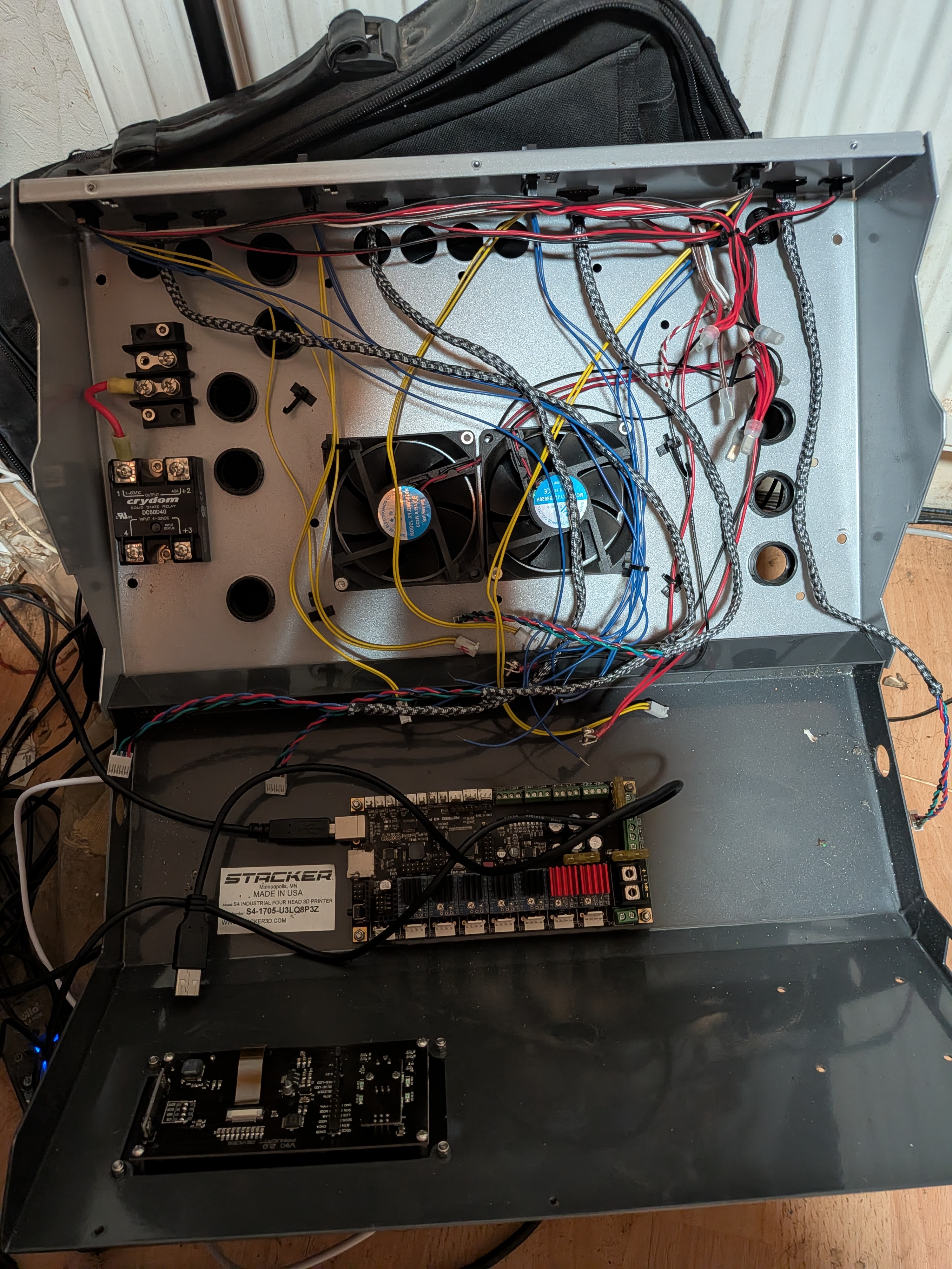
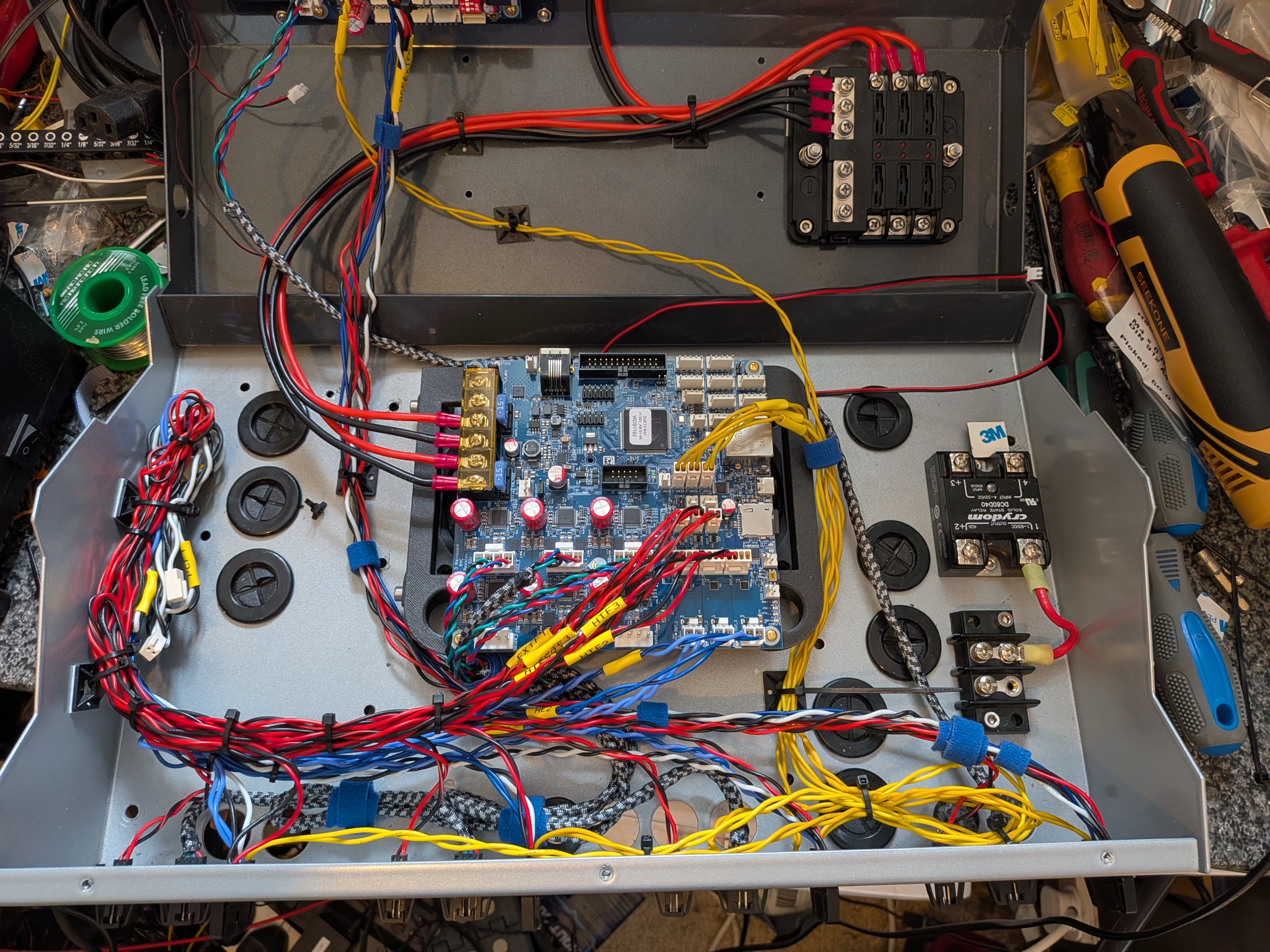
The original control arrangement was replaced by a Duet 3 6HC main board with a Duet 3HC expansion board. The installation provides the I/O needed for four independent extrusion systems, heaters, fans, probing, status lighting and service functions. The electrical bay was rebuilt and labelled, with revised fan allocation and a cleaner service layout.
High-speed 24 V GDSTIME 5015 blowers were introduced for effective part cooling, while the working original fans were retained as spares. The controller and enclosure cooling were also tested through dedicated macros.
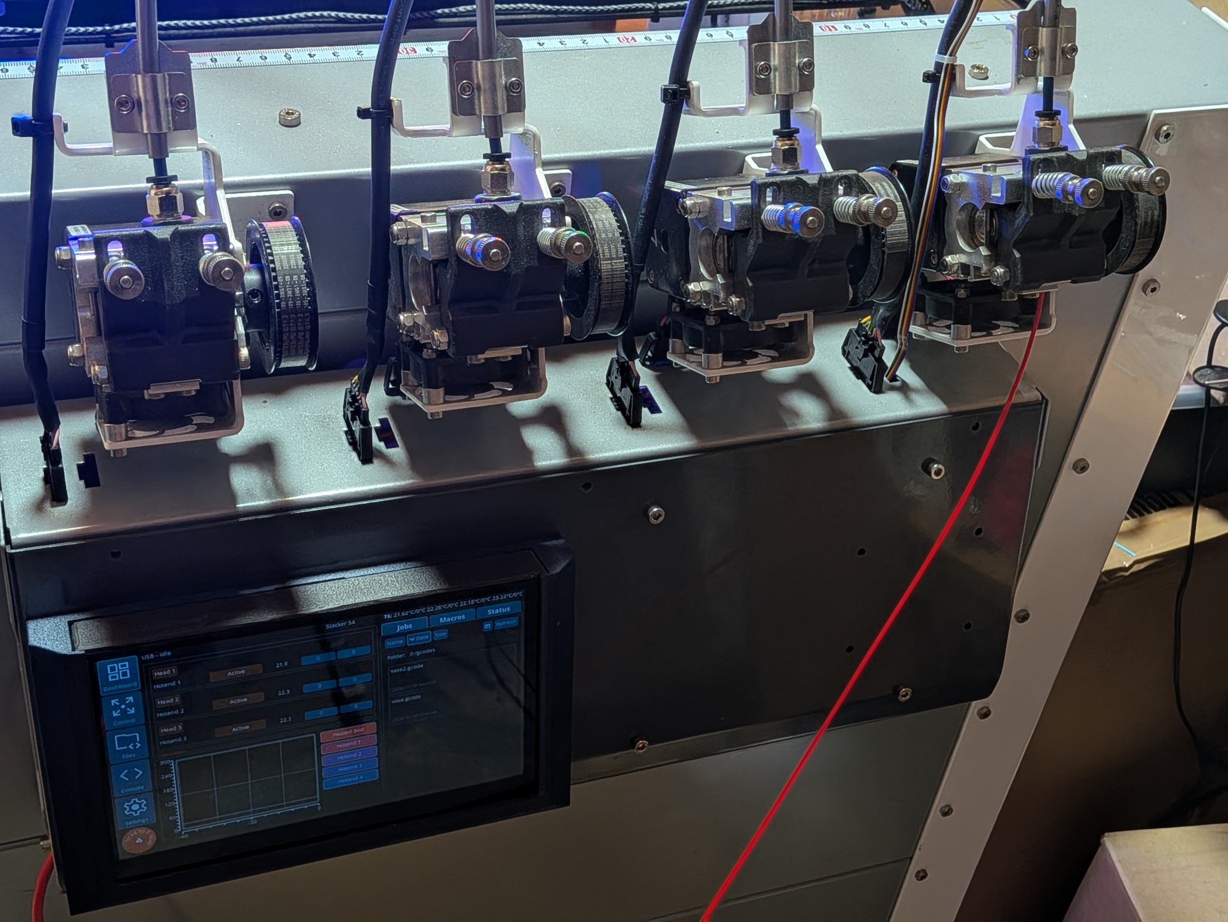
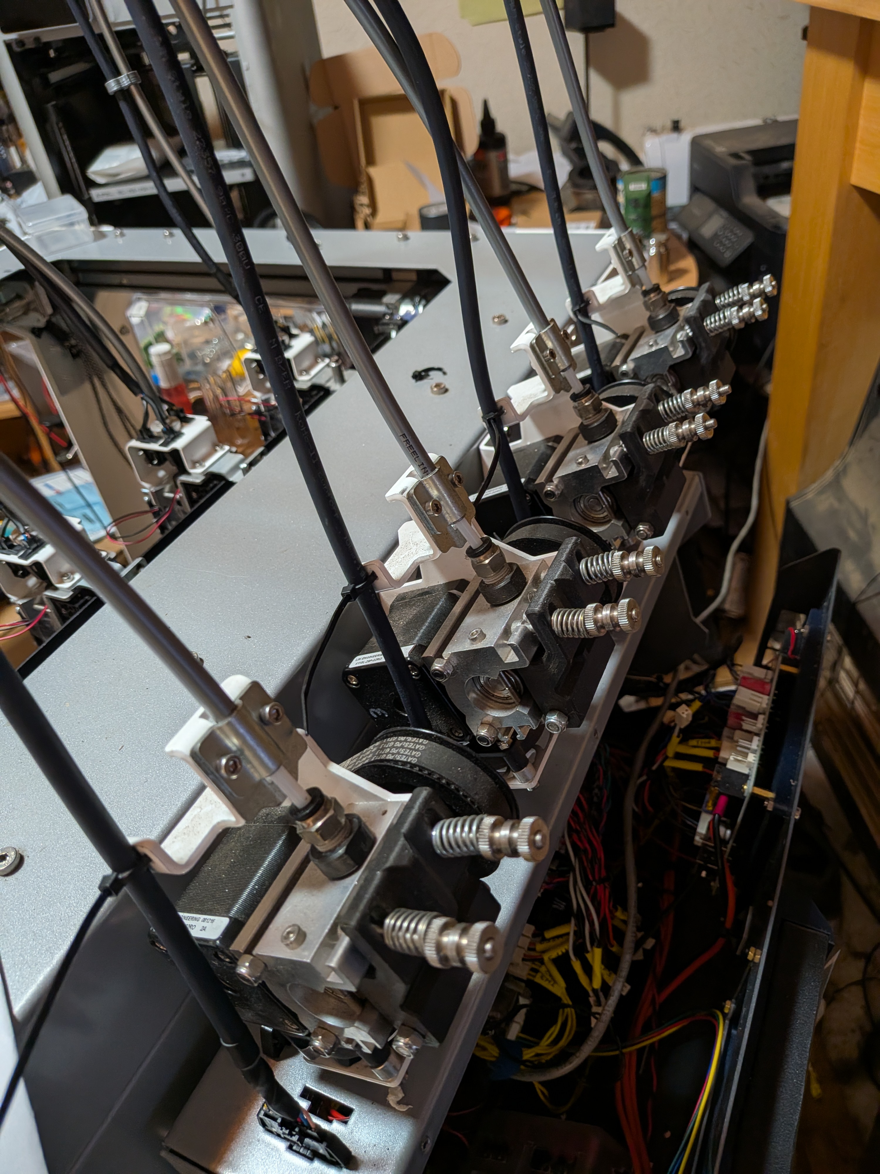
Four E3D Revo 6 toolheads
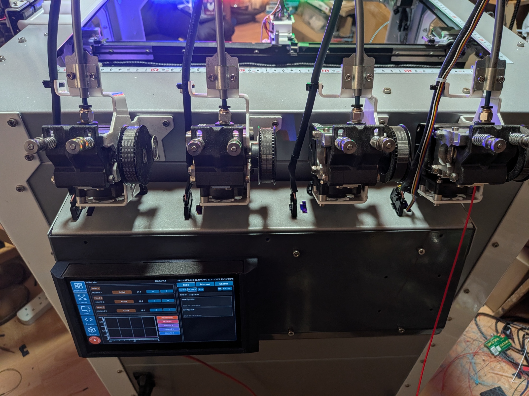
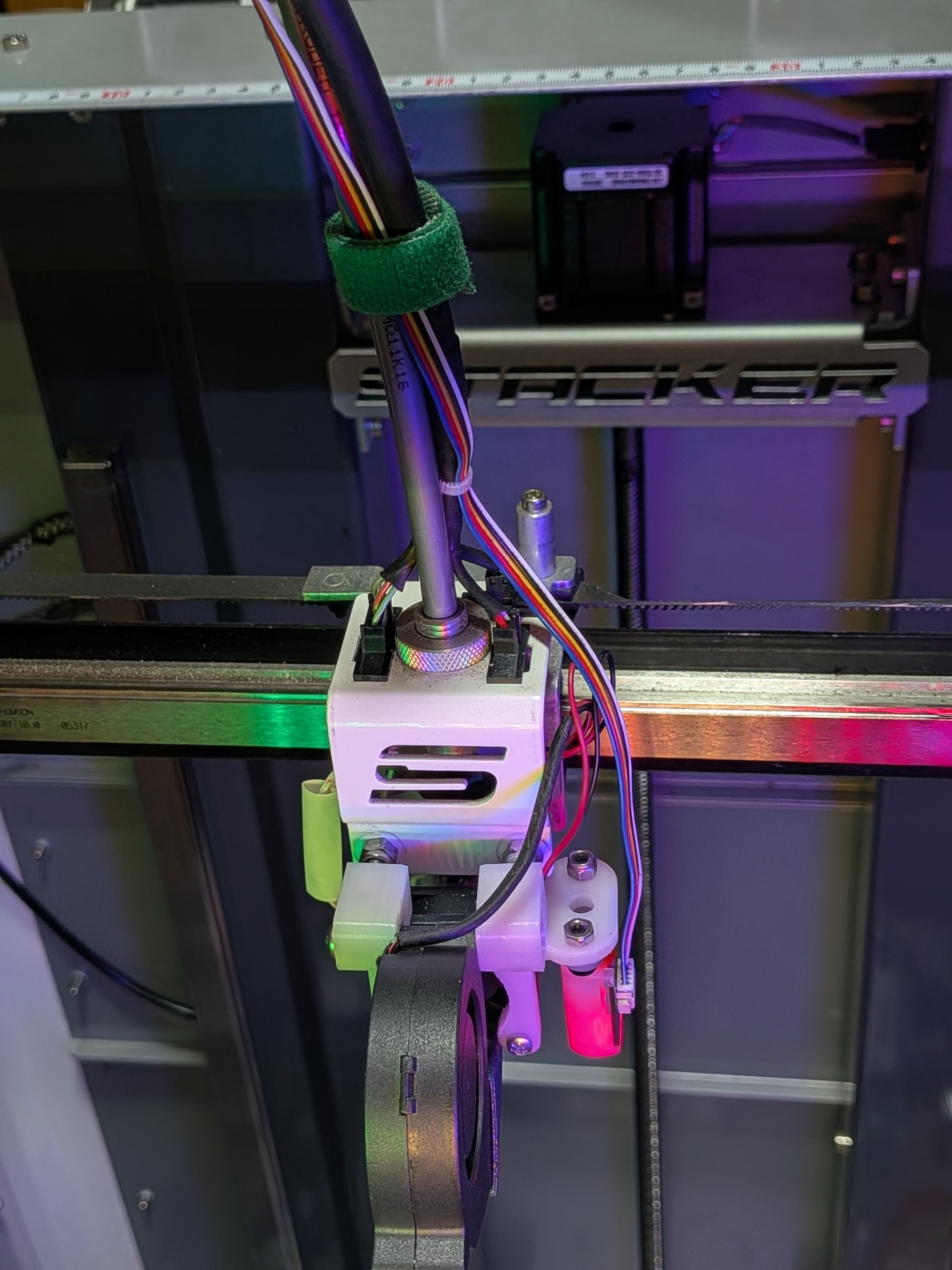
All four tool stations were rebuilt around E3D Revo 6 coldside and nozzle assemblies. Custom cooling arrangements, fan brackets and ducts were developed to suit the Stacker carriage rather than forcing a generic toolhead design into the machine. Each head retained independent temperature, extrusion and part-cooling control.
The long Bowden paths were measured individually: 985 mm for T0, 1000 mm for T1, 1005 mm for T2 and 1010 mm for T3. Auto-load and auto-unload routines now use tool-specific distances. Loading stops 15 mm short of the nozzle, purge completes the path, and the software retraction is applied immediately when purge is accepted.
The final installation also introduced new tool umbilical cables and Capricorn XS PTFE tubes throughout the four extrusion paths.
A safer approach to homing, levelling and mesh compensation
A heavy moving bed and four toolheads demand more than ordinary desktop-printer macros. The final system includes guarded Z0 recovery, safe bed lowering, parked-position checks, clear-bed prompts and head-count-specific motion limits. A bed-to-gantry procedure uses three matched 50 mm blocks to establish the mechanical relationship independently of nozzle height.
The three-point bed can then be fine-trammed through a guided procedure that reports which screw to turn, how far, and whether to turn left or right when viewed from the front. Nozzle assemblies are aligned afterwards using a 0.20 mm feeler gauge and colour-referenced tool prompts.
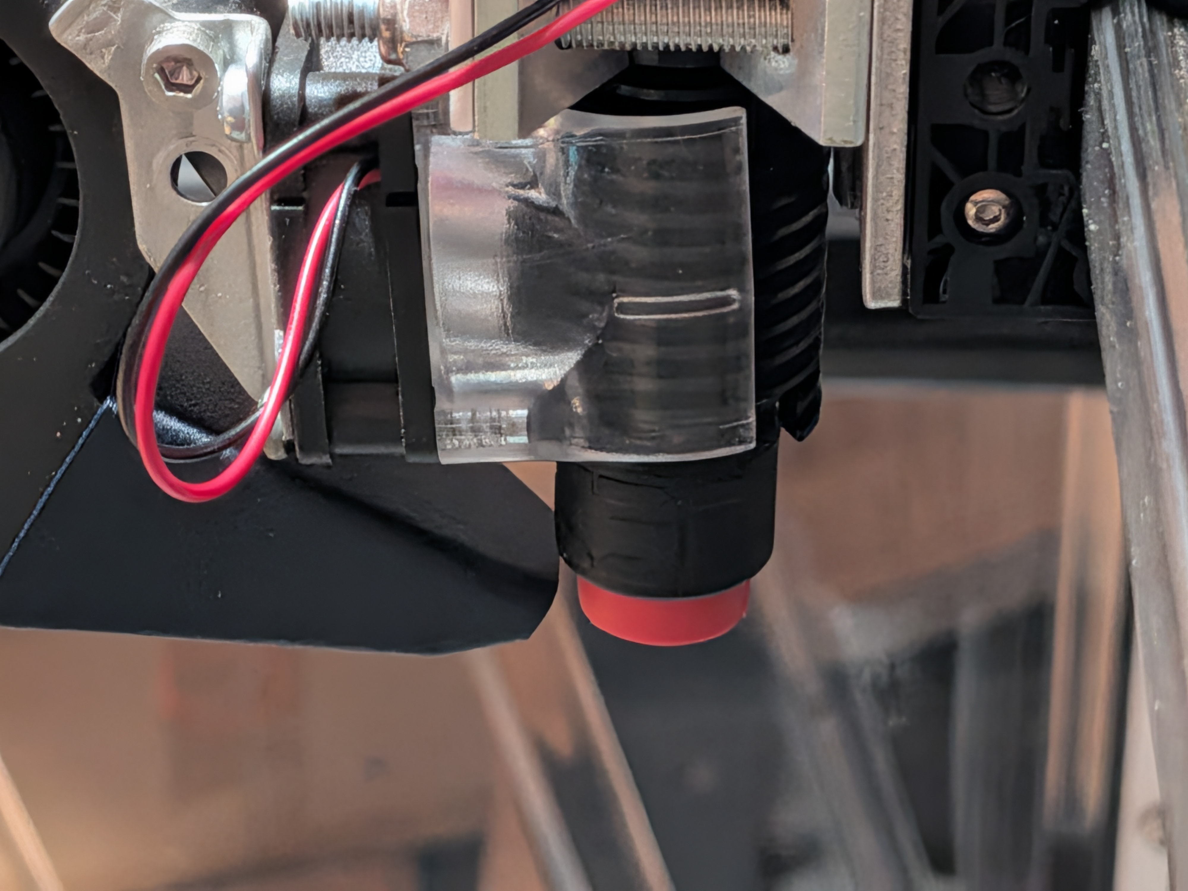
BLTouch mesh creation and loading are deliberately restricted to the single physical T0 configuration. Tools 1, 2 and 3 must be removed before probing. The configured 25-485 mm by 25-340 mm grid contains 70 points. This prevents mesh compensation from introducing nozzle-strike risk in three- or four-head operation.
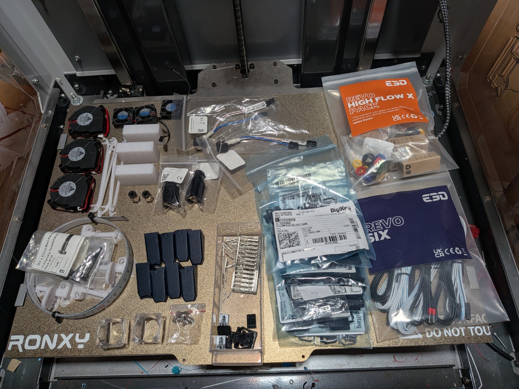
A new PEI spring-steel build surface
The original BuildTak-style print surface was replaced with a modern PEI-embedded spring-steel sheet. Tronxy supplied the plate as a 600 x 600 mm sheet, so it had to be carefully measured, cut down and edge-finished to fit the Stacker S4 bed correctly.
The new removable surface gives the refurbished machine a more practical production bed, easier part release and a serviceable replacement surface. Its installation was followed by bed-to-gantry levelling, nozzle-height alignment, three-screw tramming and fresh cold and heated mesh checks.
Machine-state lighting that communicates
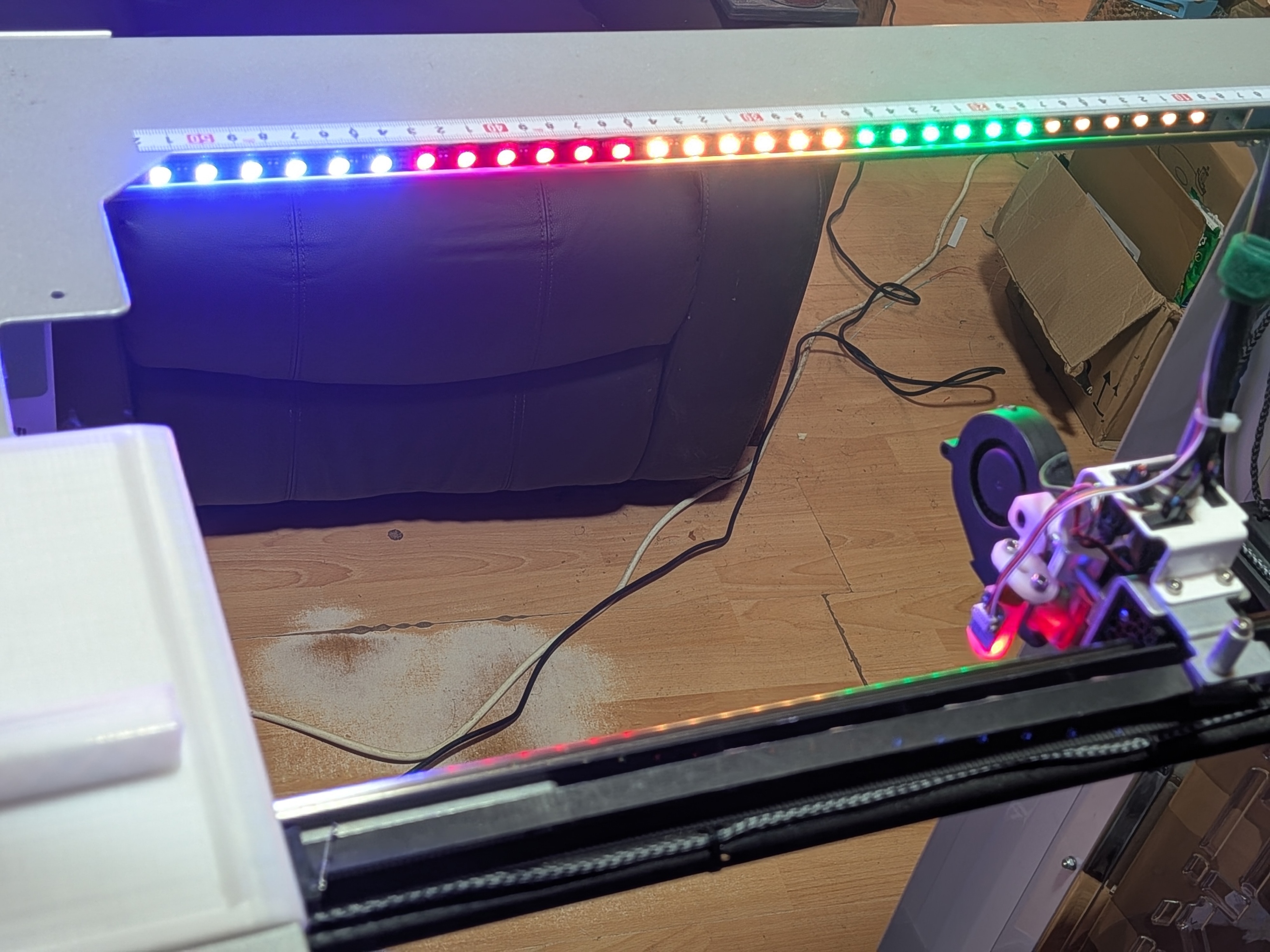
The addressable RGBW system is part of the operating interface, not decoration. Sixty LEDs are divided across the fitted strips and provide tool identity, progress, pause, warning, parking and completion states. T0 is green, T1 yellow, T2 red and T3 blue. Calibration uses cyan followed by warm white; faults flash red; pause is amber; progress moves from blue to green.
The parking sequence gives four amber flashes before movement, solid amber while the bed moves, four amber flashes after parking, two green confirmation flashes and finally normal warm white. A Uni3DVerse DWC inspection-light plugin also gives the operator a 60-second white-light view of the print, then restores the current progress or status display automatically.
Resonance testing and input shaping
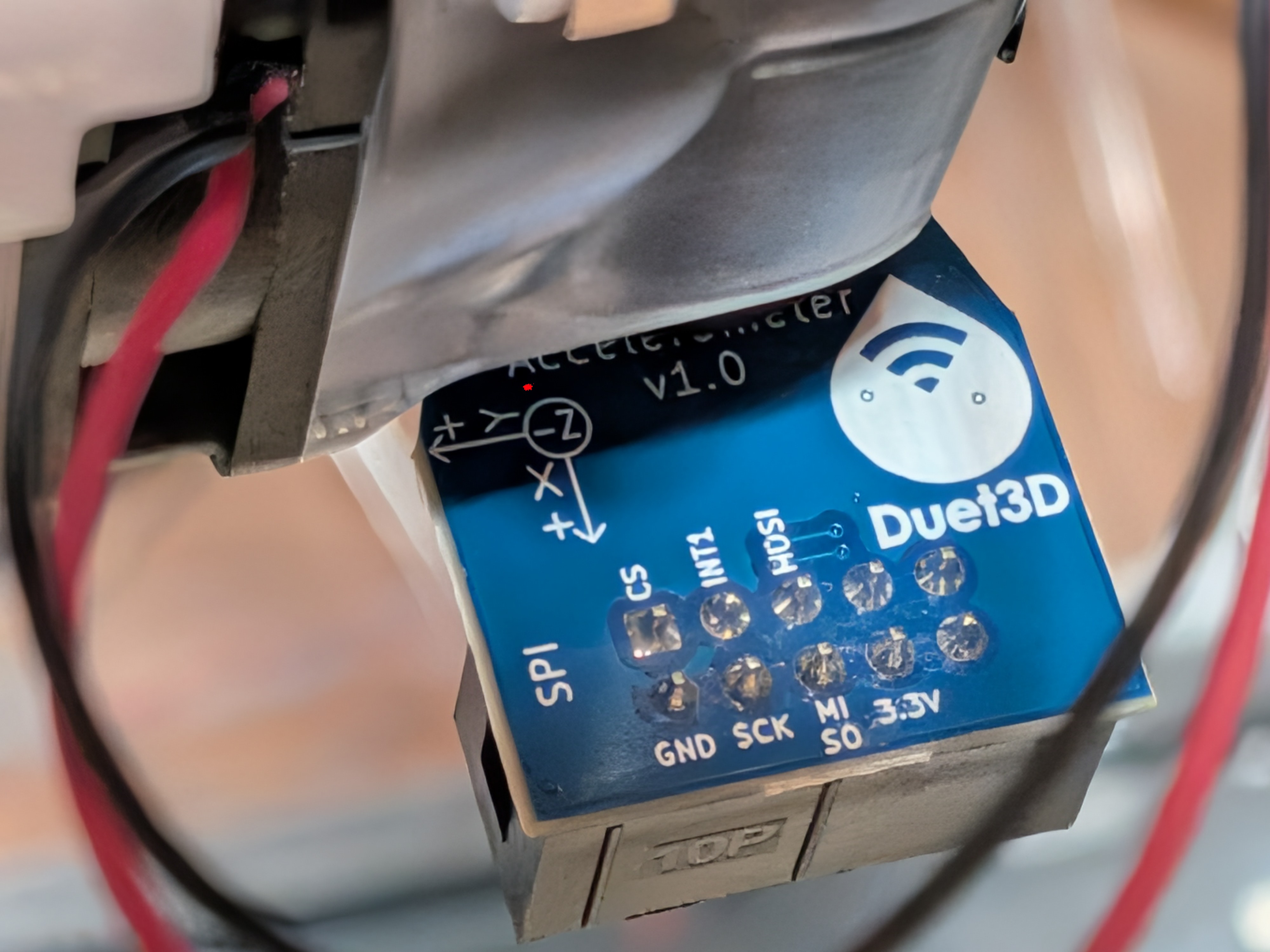
A Duet3D accelerometer was installed and tested with a restricted four-head movement routine. Commissioning uncovered a cable-orientation issue: on this installation the ribbon stripe had to align with pin 10 rather than the expected pin 1 orientation for the sensor to power correctly. That finding was verified before resonance testing continued.
The measured result supported ZVDD input shaping at 42 Hz, now enabled with M593. Print comparison showed no adverse change in surface appearance. The machine had already produced a very clean model without visible ringing, so the shaping setting is retained as a measured safeguard rather than a substitute for good mechanics.
Software, profiles and guided operation
The printer now supports one-, two-, three- and four-head operating modes, including copy-tool selection through Duet Web Control. Head-count profiles apply the correct safe movement envelope and lighting state. Simplify3D and Orca profiles were organised separately, and RepRap-compatible relative extrusion was adopted for the rebuilt workflow.
Operator macros cover filament loading, unloading and purging; print-mode selection; bed-to-gantry levelling; three-screw tramming; cold and 60 C mesh creation; mesh loading and disabling; nozzle alignment; BLTouch recovery; service positioning; safe shutdown; Z0 recovery; fan tests; RGBW tests; parking tests and a complete no-motion status test. Sequential messages close before the next instruction opens, avoiding stacked confirmation windows.
A separate Stacker S4 Automatic Uploader customer installer was developed to connect Simplify3D or OrcaSlicer to the Duet. Version 1.3 tests the connection and 0:/gcodes destination, watches the selected export folder, detects completed files, avoids re-uploading unchanged files and prompts before overwriting changed files. Upload Only is the recommended safe default; Upload and Run remains an explicit customer choice and operates only when RepRapFirmware reports that the printer is idle.
Mechanical service tools and workshop solutions
Several small problems required custom engineering rather than catalogue parts. Linear-carriage transfer tools and a matching Stacker storage base were modelled in Fusion 360 after the installed rail profile was measured and checked against the runner block. These printed tools allow carriage blocks and tool assemblies to be removed without losing their bearings.
Toolhead positions and gantry reference marks were established for two-, three- and four-head configurations. Cooling ducts, brackets and service clearances were iterated physically on the printer, with changes retained only after fit and motion checks.
Final tool parking arrangement
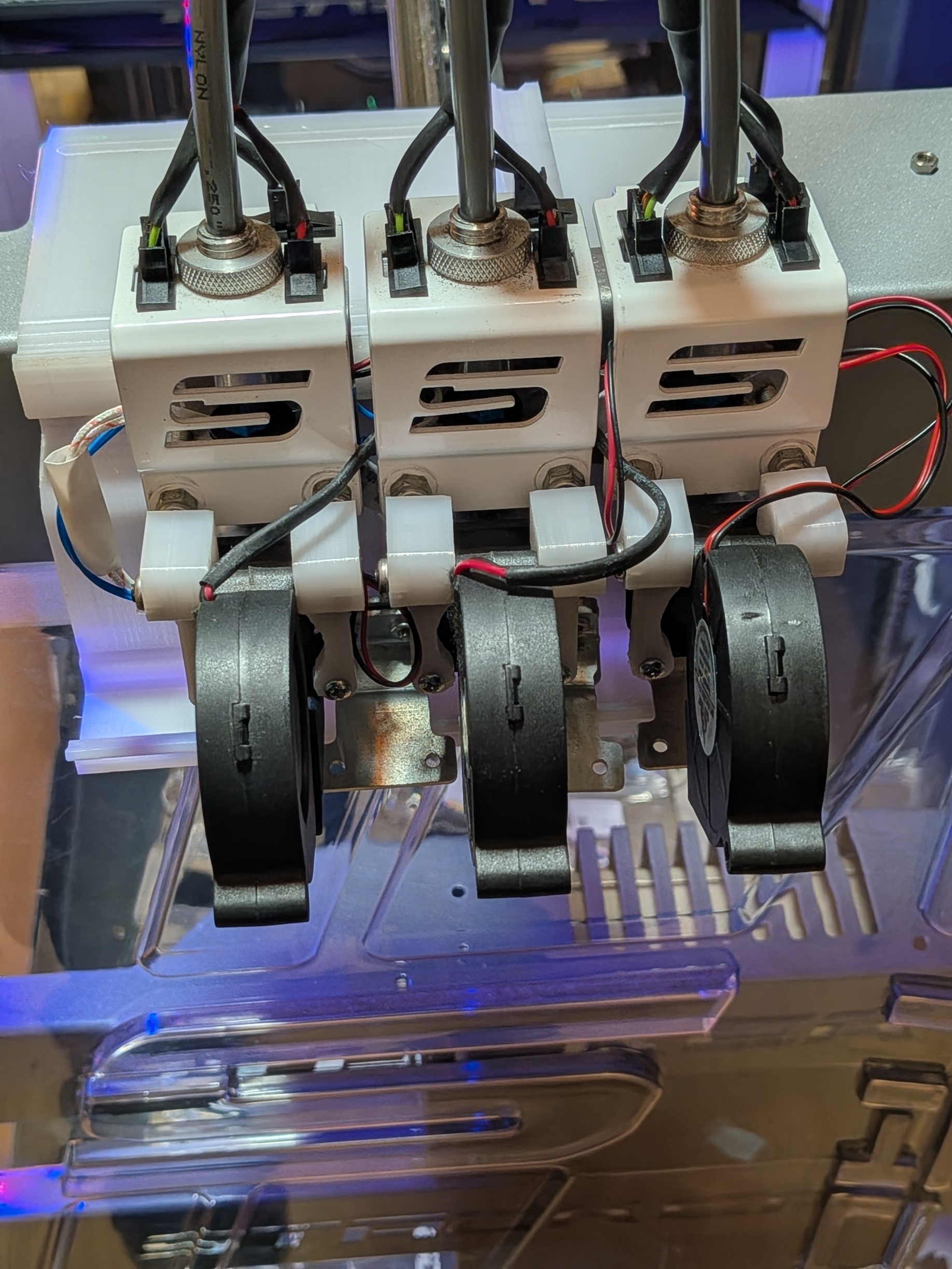
Tools 1, 2 and 3 now have a revised parking area that supports the completed fan shrouds and keeps the electrical and heater connections controlled when the tools are removed from the gantry.
The parking arrangement forms part of the service workflow and allows the T0-only probing configuration to be established without leaving the remaining tools unsupported.
Commissioning result
The finished machine homes, parks, probes, loads filament, identifies tools, reports faults and guides its operator through the procedures that carry the greatest collision risk. All four part-cooling channels, the complete RGBW status sequence, restricted accelerometer motion and the final print workflow were tested.
The latest 70-point mesh reduced the measured RMS bed error to 0.121 mm, with deviations of -0.216 mm to +0.327 mm across a very large moving bed. Final print testing showed a strong first-layer and clean model surfaces. The result is a substantially upgraded Stacker platform with modern control and unusually comprehensive operating safeguards.
Old and new: the visible transformation
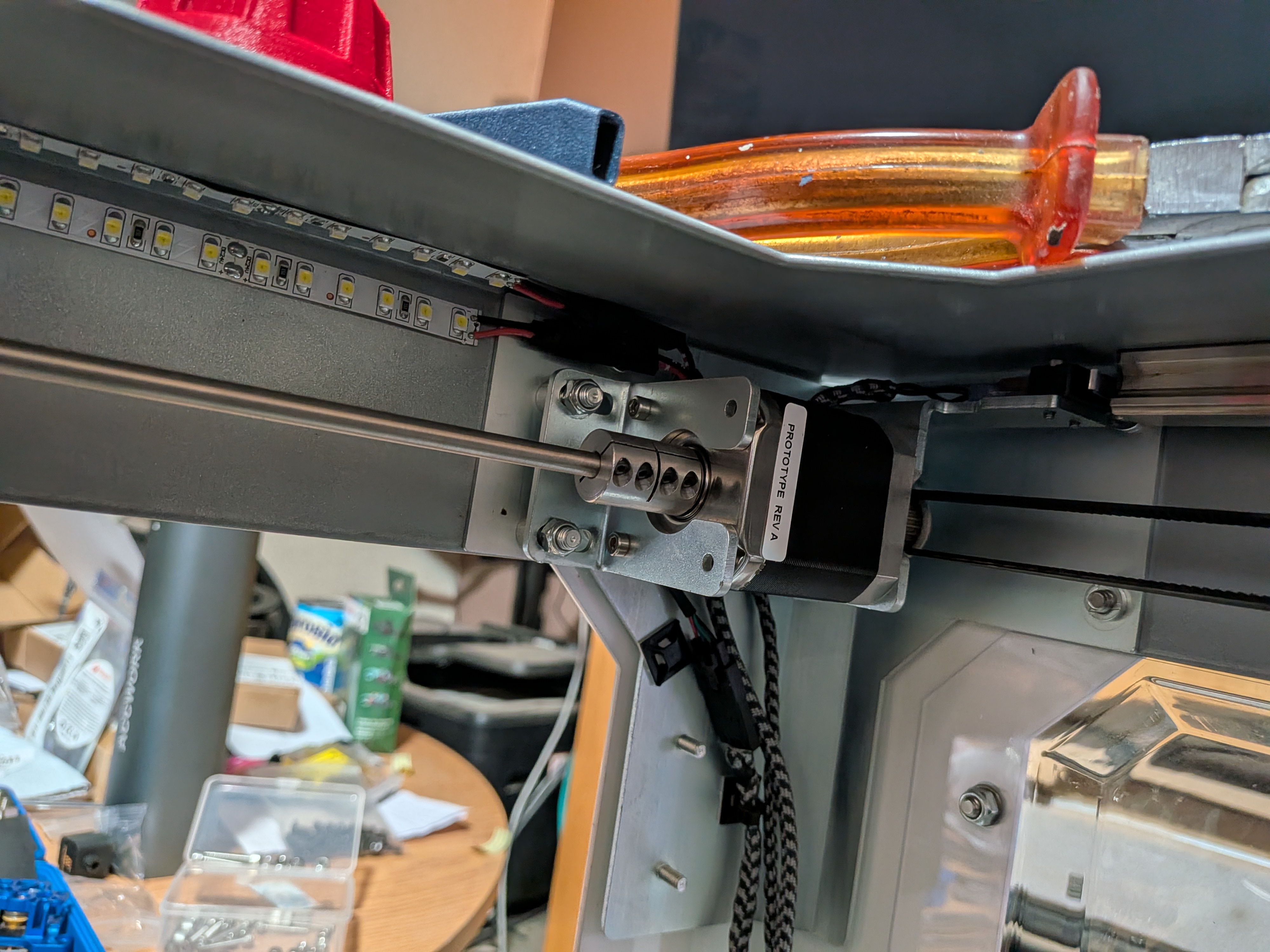
These paired photographs place each superseded development-stage installation directly beside the completed customer configuration.
Toolheads and extrusion paths
Tool 0 probing assembly
RGBW status-lighting system
What the project achieved
The Uni3D-S4R-4 preserves the scale and four-tool capability that made the original Stacker S4 distinctive, while replacing its ageing control and calibration workflow with a modern, documented system. To our knowledge, it is one of the most comprehensive Stacker S4 refurbishments completed with integrated Duet control, E3D Revo hardware, guided safety macros and operator-facing RGBW status logic.
The next phase is customer use: real production work, supported by the final-revision operations manual, calibration addenda, slicer profiles and retained service files created during commissioning.